How to Install a Breaker Panel Receptacle
Breaker Panel GFCI
Install a 20 ampere (amp) dedicated Ground Fault Circuit Interrupt (GFCI) receptacle at the breaker panel in 5 easy steps! In this case, "dedicated" means that only one device is included in the circuit. This receptacle circuit must be rated 20 amps, and ground fault protected, in accordance with the National Electric Code (NEC). All upgrades must now follow rules for new construction.
|
You'll Need:
* Access to the sides of the breaker panel * An available slot & amperage for a new 20 amp circuit breaker * 4" x 1-1/2" square metal box w/ 1/2" knock outs * 4" square metal cover for GFCI receptacle * 1/2" Metal box spacer * 20 ampere GFCI Duplex Receptacle & Breaker * Electrical tape * 12/2 Romex or 3 lengths of 12 gauge insulated/stranded copper wire * wire strippers, wire nuts, screwdrivers, pliers |
#ad |
#ad |
|
1. Remove the circuit breaker panel cover and the metal tab corresponding to the position of the new 20 amp circuit breaker you install.
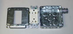 4 inch square metal box
2. Remove 1/2" knock outs in the side of the panel and the 4" metal box. Install the box with the box spacer; locking rings secured tightly, the box should not move. If there is movement after tightening locking rings, anchor the box to the wall.
 Mount coverplate
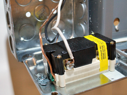
3. Wire the receptacle first (see warning); then carefully route the wire through the connecting spacer into the panel. Make no panel connections, accidental or deliberate, until the receptacle is installed! Remove the ears and bend just the threaded portion on each end of the receptacle slightly backward, then attach it to the cover plate with the machine screws and lock nuts provided. Wrap the receptacle, covering the contact screws with electrical tape to prevent a short.
4. Install the breaker, switched to the OFF position. Corner the wires inside the panel, for a professional appearance. Secure the neutral and ground wires to the bar, before securing the hot to the breaker. Pay attention! If the neutral bar is isolated from the panel, neutrals and grounds are kept separated on two or more bars, look closely and you'll see the insulators.
 Test Circuit
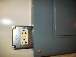
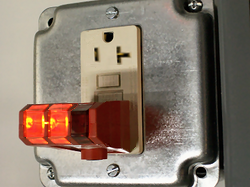
5. Install the receptacle cover plate. Switch the new breaker to the ON position and check the circuit with a GFI+Receptacle tester in the load port. Both orange indicators should light, leaving the red indicator off. Push the test button and verify that the ground fault trips. Remove the tester and reset the receptacle. Replace the panel cover, if all is well.
Tips:
* Metallic box connectors provide more stability than longer threaded fittings, with four locking rings, unless the [receptacle] box is otherwise anchored. * Finished wall? Install this dedicated GFCI receptacle, as close as possible, using 12/2 Romex and an old work box. Warnings: * Problems reported with back-wired (push-in wire receivers) receptacles & switches indicate loosening wires & arcing caused by the momentary break in circuit. Use the side screws for secure connections! Copyright 10/09/2012 All Rights Reserved. Questions? Comments? Contact Me DISCLAIMER: All Electrical tutorials are meant for those with working knowledge of electrical wiring and should not be attempted by first-time novices. Related articles: Electrical Sub Directory |
|